Thor Hydraulic Fab
and Installation
It took a
long time, but we "got 'er done"
Event Report
202001
Back to Bill Caid's Home Page
The Experience
Our initial experience
with Thor's new living quarters spanned 3 months. We
identified several issues that we wanted to address including
adding hydraulic stabilizers to prevent "house roll" when parked
and occupied. And, since the new setup did not have any tool
boxes, we needed to add extra space.
Upon our return to San Diego, we launched into what would end up
being a multi-month effort that was repeatedly put on pause due to
external causes. While it took much longer than we expected,
in the end we "got 'er done".
We selected "ProTech" as our tool box vendor since we needed
full-custom dimension boxes. These boxes are very
sturdy and robust, but quite pricey at $650 each. Since we
needed 6 boxes, the final price was substantial. To order
the boxes, we needed to find a local vendor which turned out to be
the Peterbuilt dealership in San Diego. The order took 8+
weeks to fulfill, but we used the down time to addressed
other issues. Hydraulic cylinders were ordered online and
shipped to the house. Ancillary components were acquired or
located within my local inventory (AKA my garage) and we awaited
the delivery of the boxes.
The photos below are
what we saw.
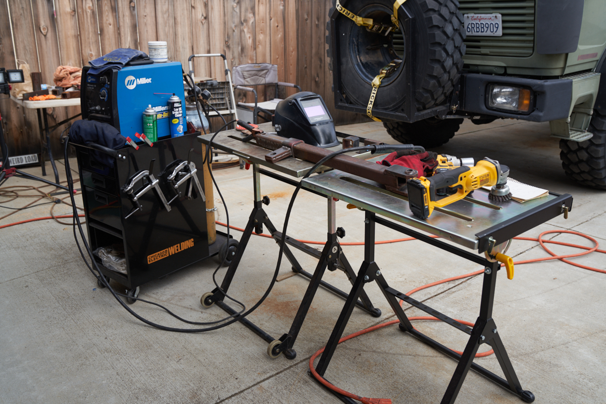
Harbor Freight had a sale and I purchased an additional welding
table for the task. Above, one of the outrigger spars is
being fabricated.
Due to the China trade tiff, delivery of my hydraulic pump was
months late. In the interim, the material was
rusting. Fully useable, but with a bit of surface
preparation.
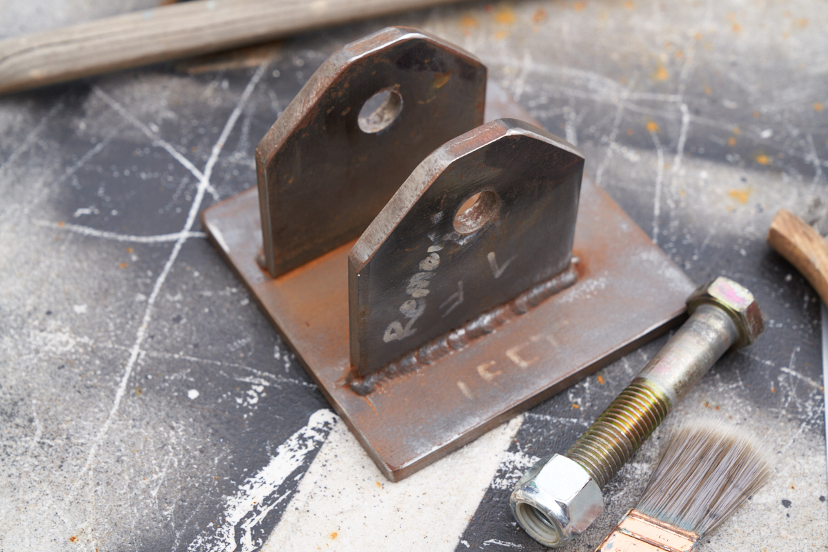
Feet for the outriggers were made of 3/8" plate.
The fork-with-eyes end attaches to the truck pivot
point. A 1/2" bolt/nut combo secures a hydraulic pivot
point. Loosen the bolt, and the collar can slide to hone
final geometry.
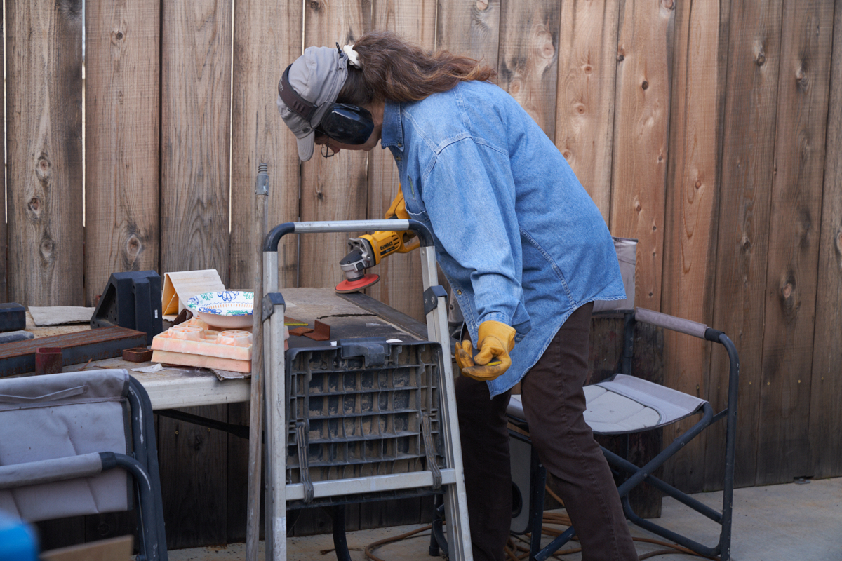
Kathleen helps with the surface preparation tasks on the 2x0.25"
truss strip.
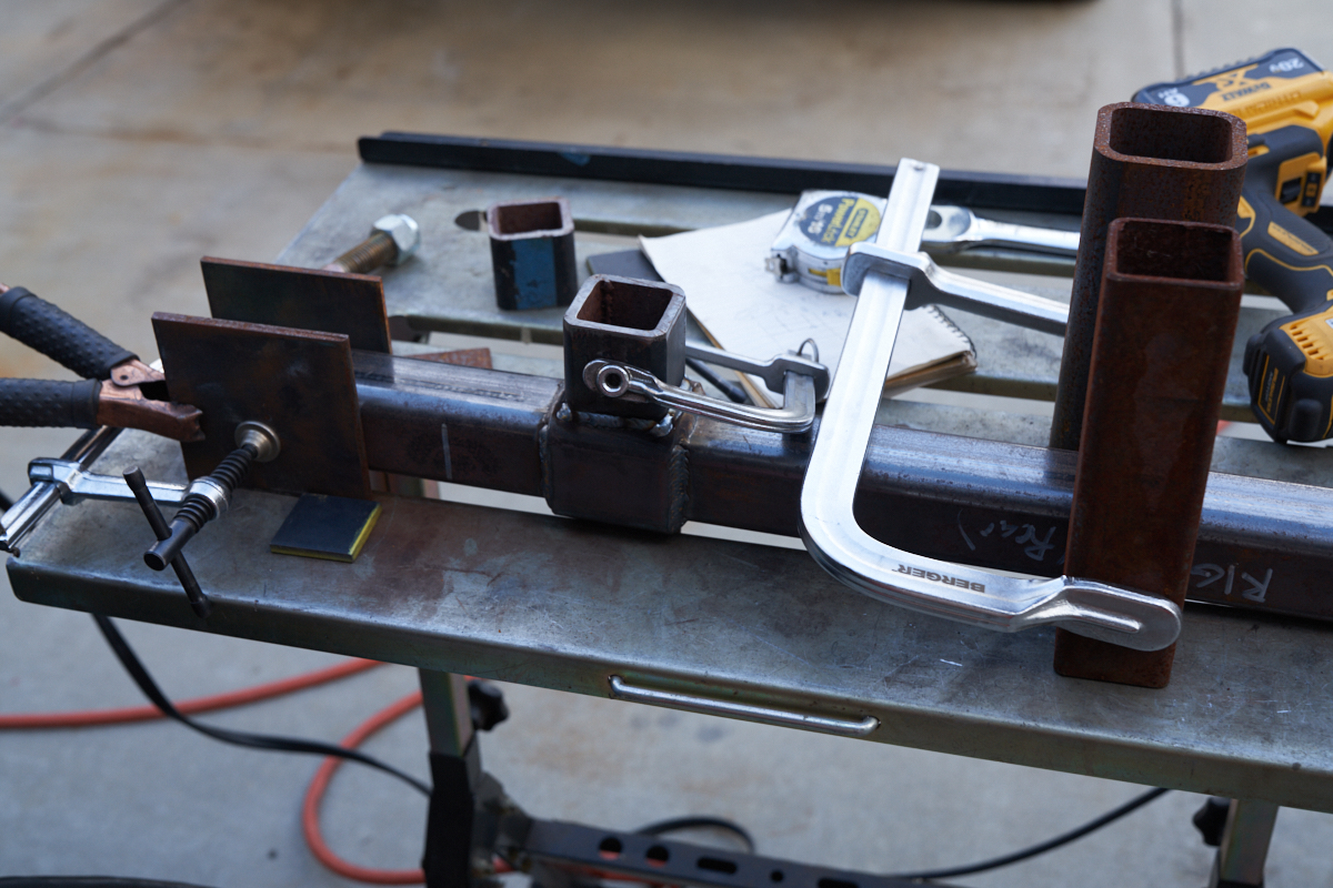
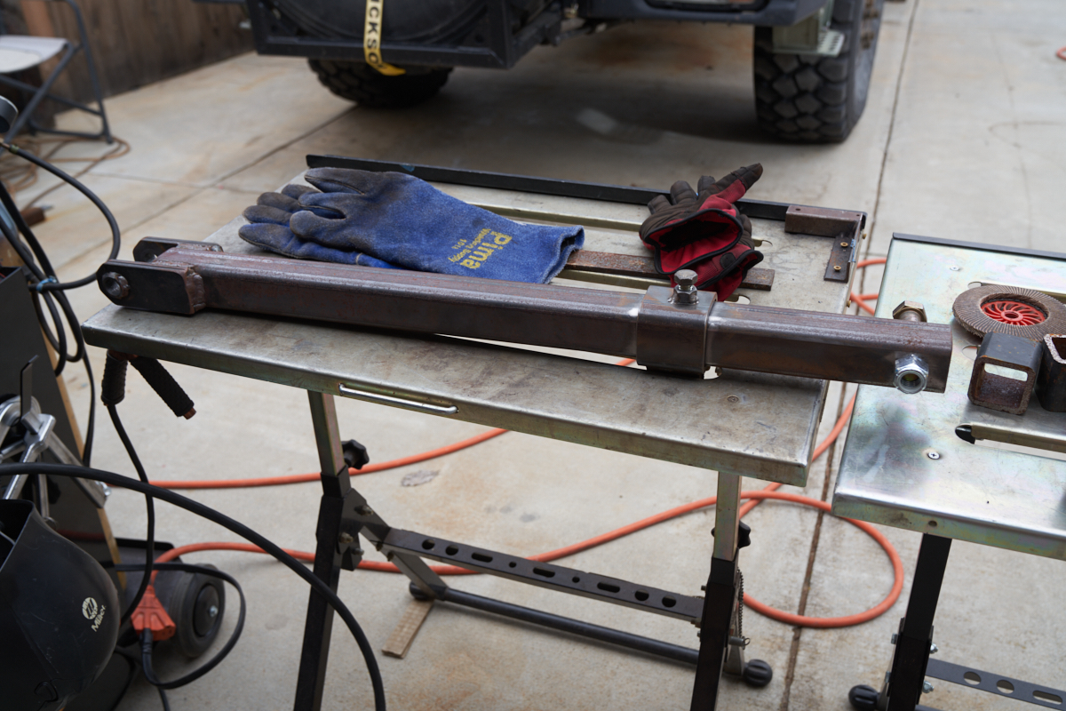
The objective of this process is to transform a 2x2 inch square
spar into a truss. Our plan was to position and tack a
strip of 2x0.25" from the end of the fork-eyes across the short
tube in the photo above and then on to the foot-end of the
spar. Our plan was to brace, clamp, tack, heat with torch,
bend and tack the far end. Our friend Kai lent me his oxy
torch for the job and it worked like a charm. Both spars
were "trussed", cleaned and painted.
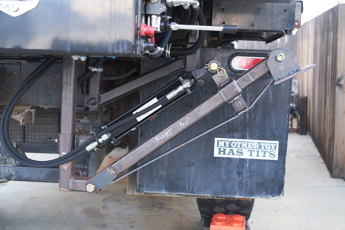
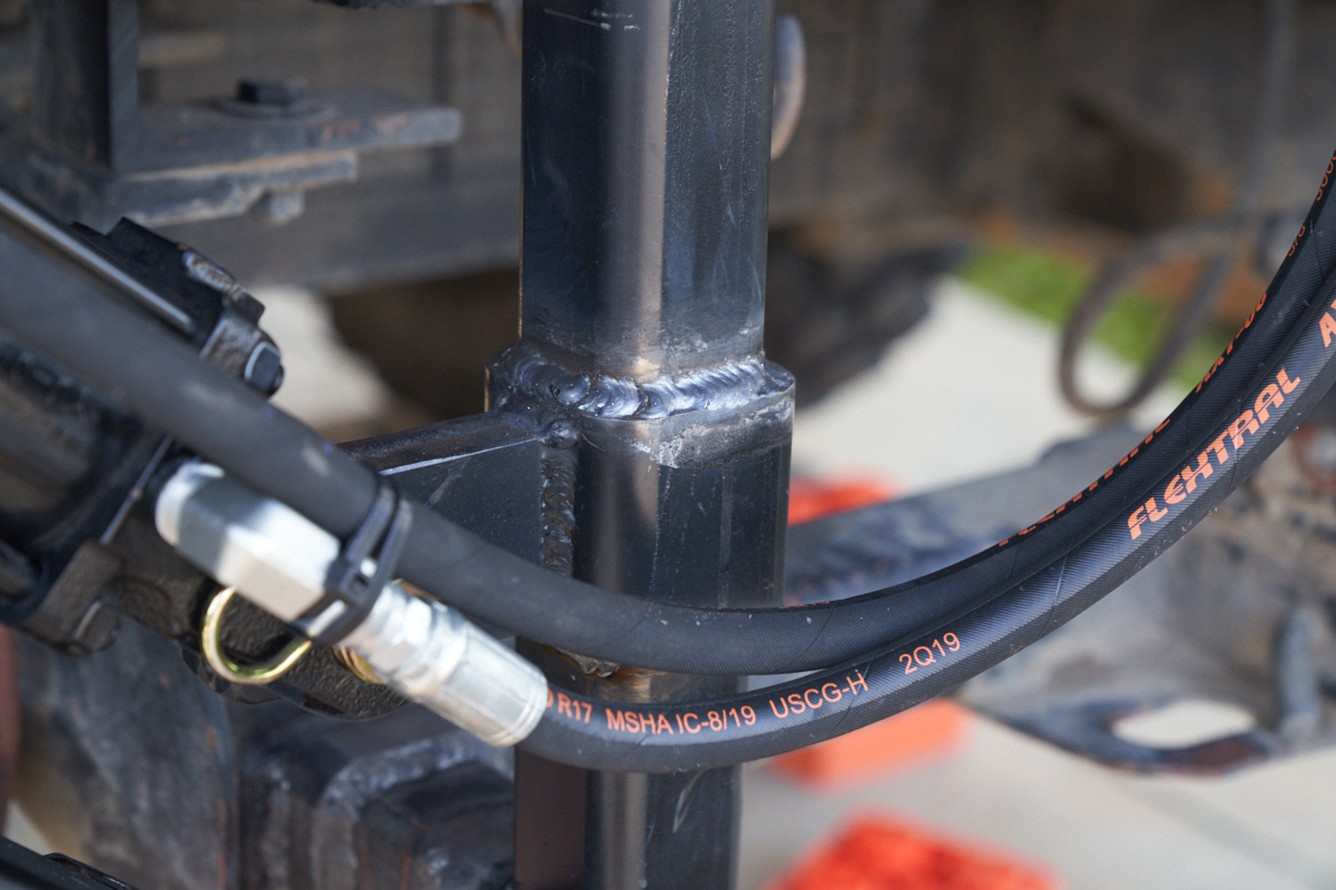
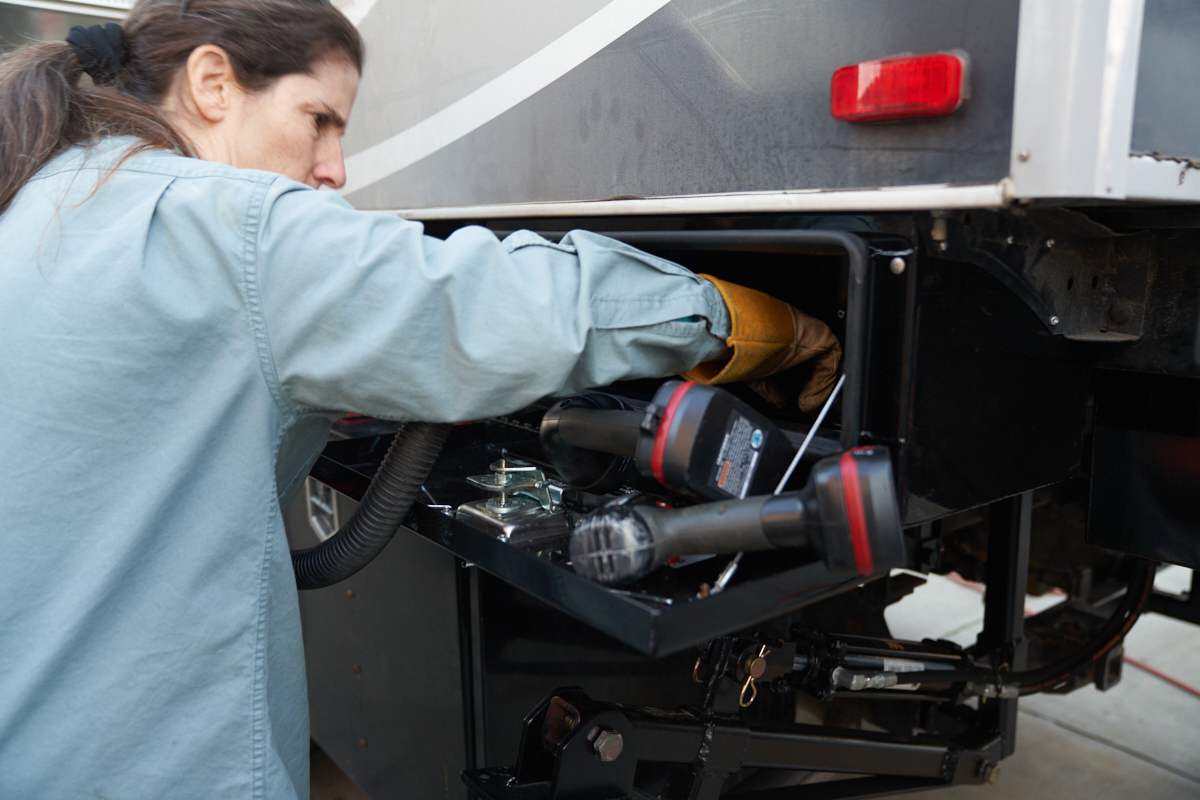
Right side installation was done as a test-fit. We had
custom hydraulic hoses made and the truck came to me.
Three times. Turns out that this was the very first new
hose installation that the guy had ever done. Every other
job was re-creating an old hose from existing equipment -- all
design choices were already made. All the guy needed to do
was reproduce the part. This installation required some
thought and planning. The hydraulic control was mounted on
the outside of the rear tool box. Both power and hoses
needed to be run to the box and the hydraulic pump was installed
in the box.
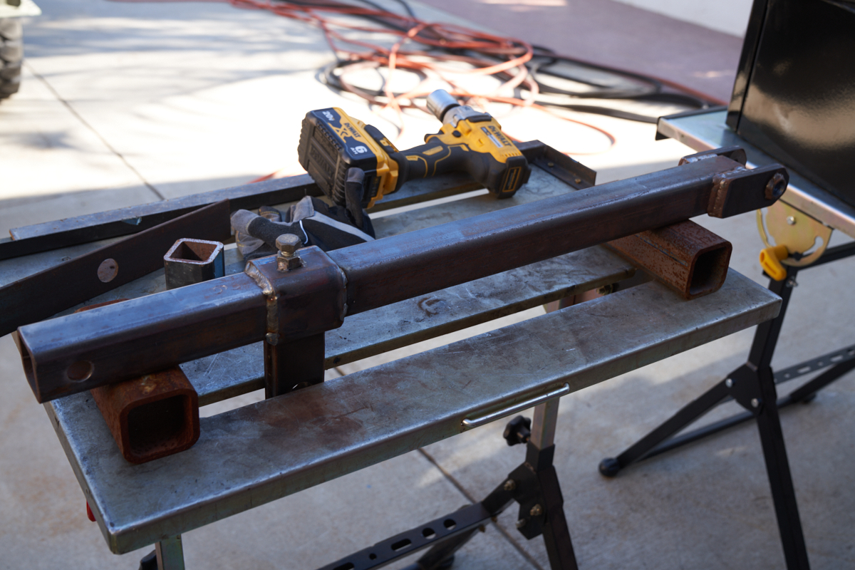
Preparing to truss the other spar.
The final adjustment decision was confirmed and the remaining
collars were hard welded to the vertical rails.
Once the collar was welded, no further changes in geometry were
possible. The sliding collars allowed us to test
adjustments to the baseline geometry and insure success.
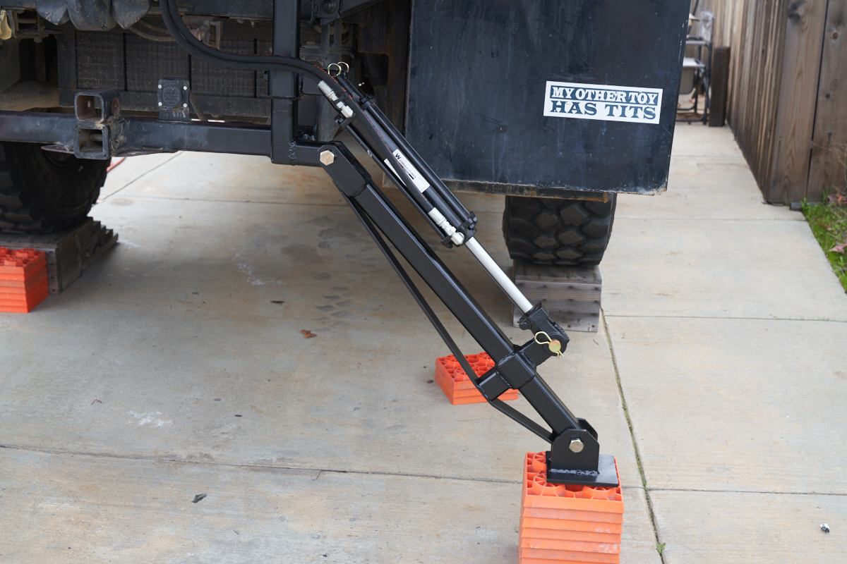
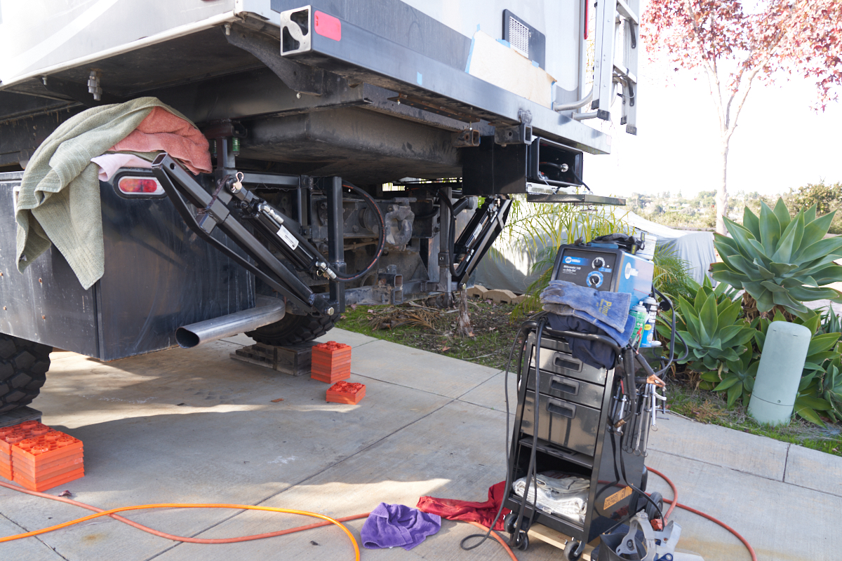
Passenger side deployment. Orange blocks were removed to
test the full range of motion.
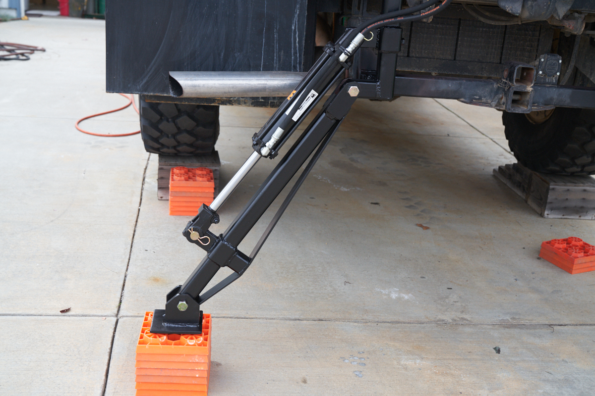
Driver side deployment.
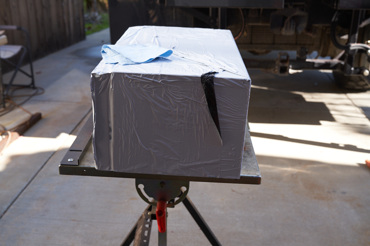
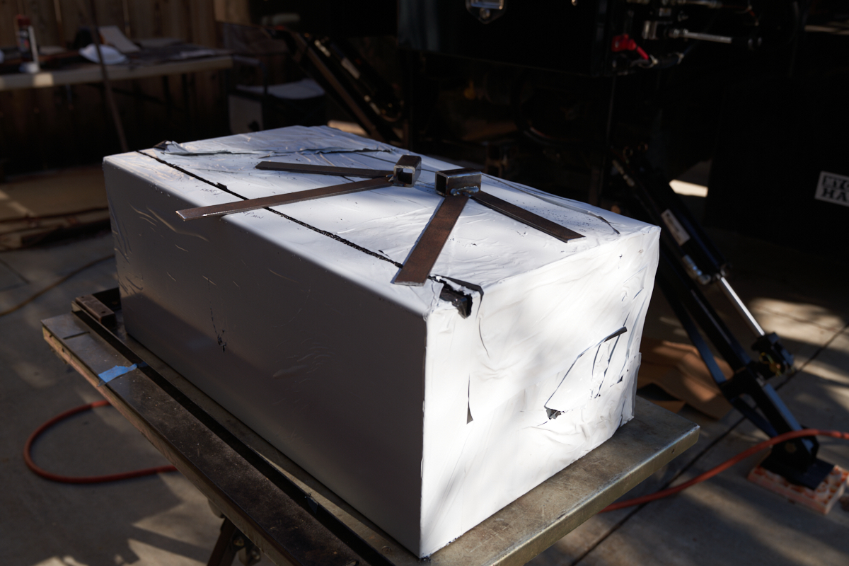
Next, we moved on to mounting the custom tool boxes. These
boxes were beautiful, if you can say that word in the same
sentence as tool box. Mirror smooth and nary a scratch,
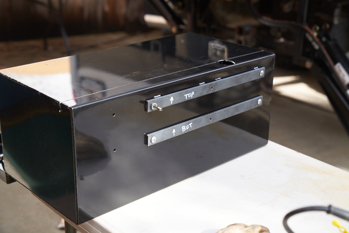
our first action was to violate the box. We initially left
the protective plastic on the box . To get the boxes to
mount flush to the bottom of the trailer body, a slot will have
to be cut in the top of the box. For the slot, I used a
Makita worm-drive saw with a Diablo metal blade.
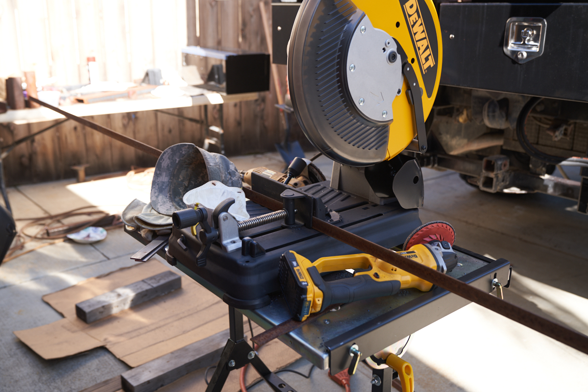
The cold-cut saw was used to prepare shims and braces.
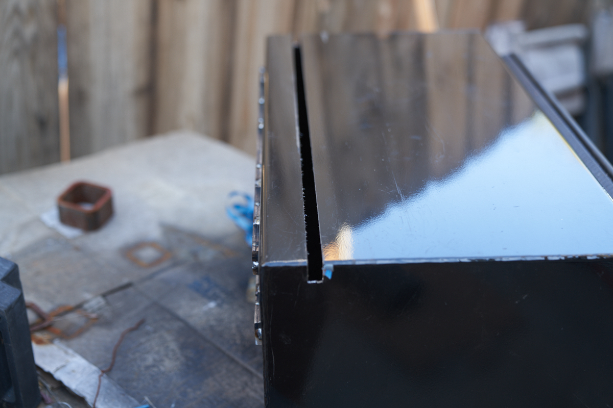
The slot in the top-rear of the box was cut and left/right
weld-on braces were fabricated.
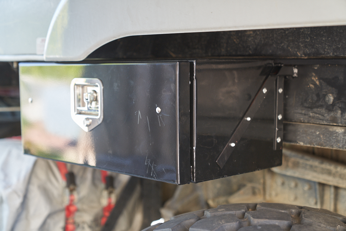
We thought we were being thwarted by the radius of the trailer's
z-beam. It took several cuts to get the real dimensions
correct.
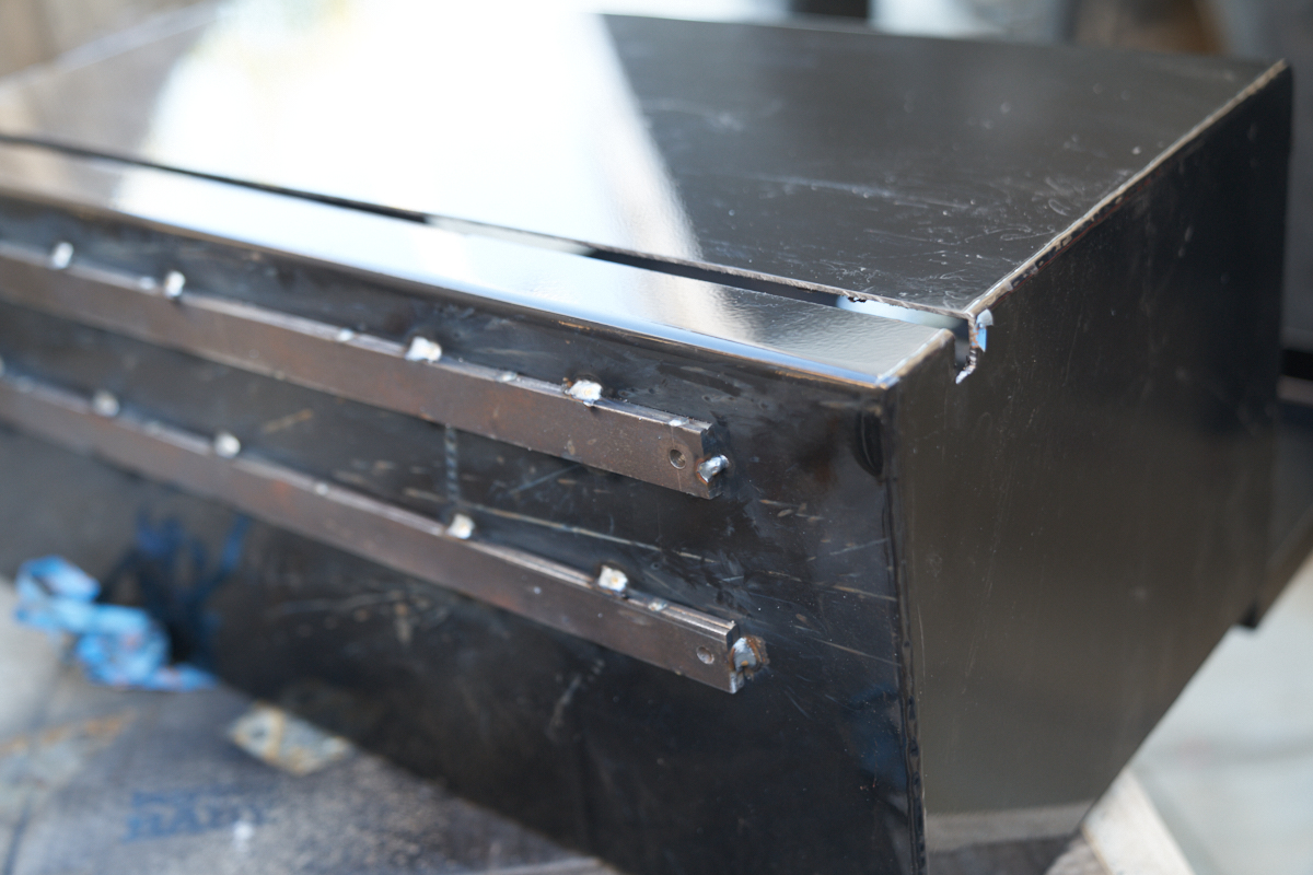
The real issue, it turns out, was not the radius of the beam but
rather some interferences lower on the frame. To make both
problems go away, a 1/4" standoff was welded to the back of the
box. Holes were drilled to allow correct positioning and
grounding of the welder. During installation, the box will
be pop-riveted to the weld-on braces and flange of the beam.
Not surprisingly, the first box was the hardest. The first
box was attached to an in-situ rear brace, the trailer frame and
a weld-on brace. Above, Kathleen is cleaning the chips and
curls from the saws and drills.
The next box was cut and stand-offs were welded on. Note
that this box also required a clearance hole for one of the
bolts that hold the house to the frame.
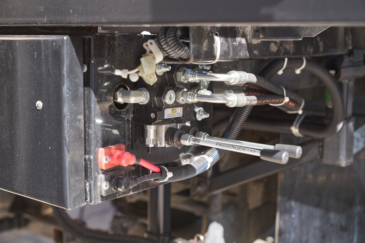
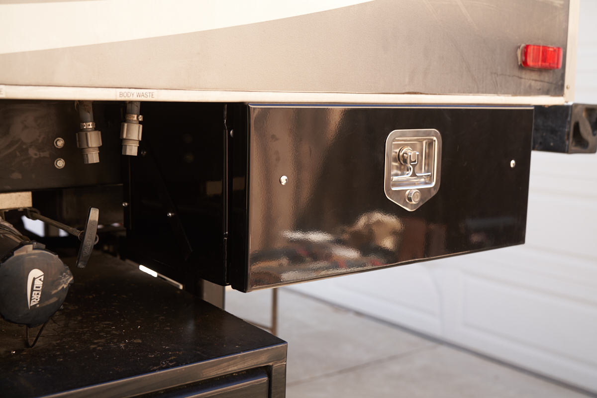
The final external configuration. The hydraulic tool box
is attached to the 4x4 blackwater tube holder and the hydraulic
controls are attached to the tool box. Electrical enters
the box at the bottom left.
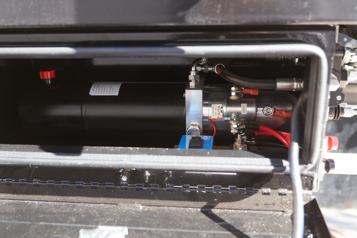
Inside the box is the hydraulic pump and support circuits
consisting of the control switch and a 150A high-current
fuse.
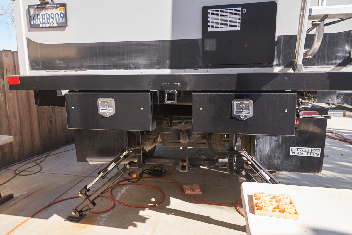
View of both rear tool boxes with stabilizers deployed.
Two weld-on braces were needed for the next box: one fore and
one aft.
The rear-ward box was a snug fit.
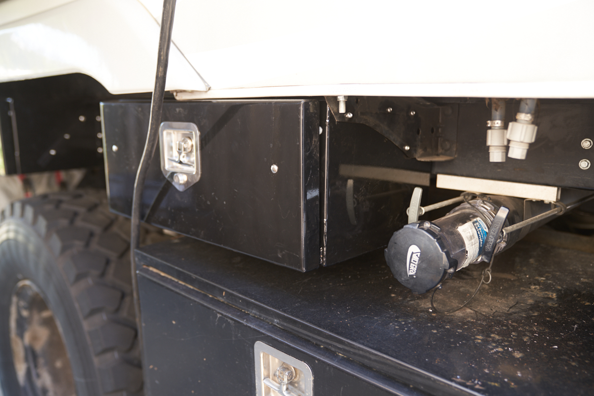
Where possible, existing braces were co-opted for mounting the
boxes.
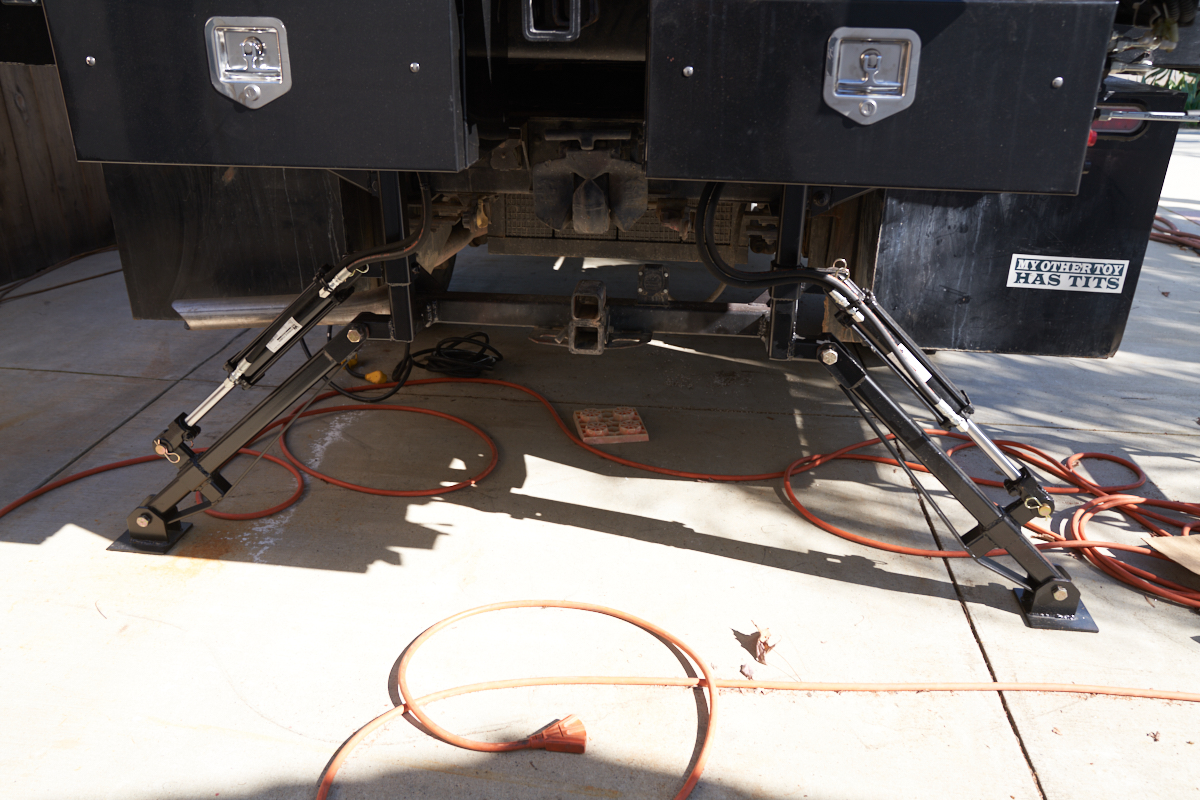
Rear view with stabilizers deployed.
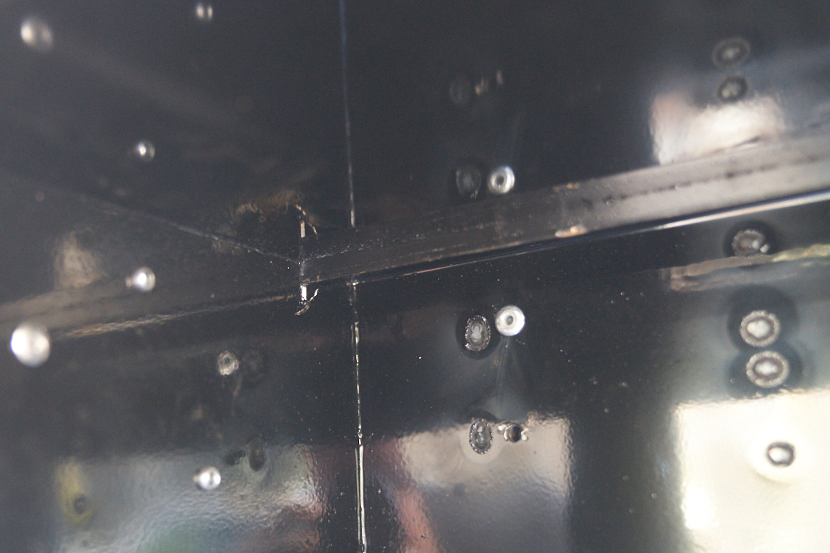
A final view of the intrusion of the z-beam into the tool box
interior. These slots will be sealed with black RTV. The pop rivets at the
rear of the box are visible (one hole yet to be riveted) and the
discolorations are from welding the stand-off to the rear of the
box.
This was a ton of work and
involved facing some unseen challenges (extended delivery times
due to trade issues). These projects can be very time
consuming because of the details required for a good job.
Kathleen hung in there like a trooper and supported me to the end.
Back to Bill Caid's Home Page
Copyright Bill Caid 2020. All
rights reserved.
